Well, I recently stumbled upon something truly invaluable for all you EZGO DCS owners out there: the EZGO DCS wiring diagram.
Trust me when I say that having an EZGO golf cart wiring diagram is a game changer.
In this article, I’ll break down the essentials of the EZGO DCS wiring diagram. Thereby empowering you to tackle electrical issues and make modifications with confidence.
EZGO DCS Wiring Diagram
This is the EZGO DCS wiring diagram:
 1")
Understanding the EZGO DCS Wiring Diagram
The EZGO DCS wiring diagram is a powerful tool that provides a visual representation of the cart’s wiring setup. It’s like having a roadmap that guides you through the intricate network of wires, helping you understand how everything connects and functions.
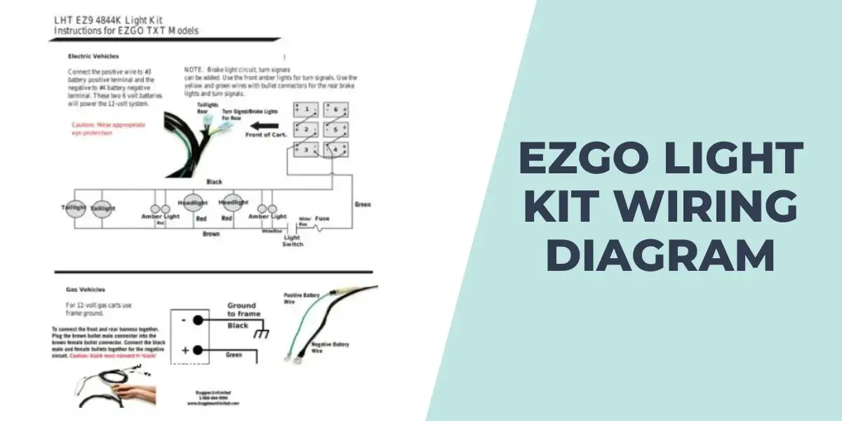
For a comprehensive guide on wiring an EZGO light kit, you can refer to the EZGO Light Kit Wiring Diagram.
Elements of the EZGO DCS Wiring Diagram
These are the key elements of the EZGO DCS Wiring diagram:
- Batteries: The golf cart is typically powered by multiple batteries connected in series or parallel to provide the necessary voltage and current.
- Key switch: This is the main power switch that controls the overall power supply to the cart. It’s usually located on the dash and can be turned on or off using a key.
- Solenoid: The solenoid acts as a switch to control the flow of high current from the batteries to the motor. It’s usually activated by the key switch or the accelerator pedal.
- Controller: The controller is the brain of the DCS system. It receives input from various sensors and switches, and it regulates the power going to the motor to control the cart’s speed and direction.
- Motor: The motor is responsible for driving the wheels of the golf cart. It converts electrical energy into mechanical energy to propel the vehicle.
- Accelerator pedal: The accelerator pedal controls the speed of the golf cart. When pressed, it sends a signal to the controller, instructing it to increase the power to the motor.
- Forward/reverse switch: This switch allows the cart to move forward or backward. It’s typically located on the dashboard and is used to change the direction of the cart.
- Wiring connections: The diagram will show the various wires and their connections between the different components. Different colors and labels may be used to differentiate the wires.
For detailed information on the EZGO solenoid wiring diagram, click here.
How to Troubleshoot Common Issues Using EZGO DCS Wiring Diagram
Follow these steps to troubleshoot common issues using the EZGO DCS Wiring Diagram:
- Identify the problem: Determine what specific issue you are experiencing with your EZGO DCS golf cart. It could be a problem with the motor not running, no power to the cart, intermittent power loss, or any other electrical malfunction.
- Inspect the wiring: Carefully examine the wiring harness, connectors, and cables for any signs of damage, loose connections, or corrosion. Ensure that all connections are secure and tight.
- Trace the affected circuit: Using the wiring diagram as a guide, trace the circuit related to the issue you are facing. Follow the path of the wires from the battery to the component involved, such as the motor, controller, solenoid, or key switch.
- Check voltage and continuity: Use a multimeter to measure the voltage at different points along the circuit. Verify that power is flowing correctly and that there are no voltage drops or interruptions. Also, check for continuity (the unbroken path for current flow) in the wires and connections.
- Test components: If the wiring and connections seem fine, you may need to test individual components. Refer to the wiring diagram to identify the relevant components and their connections. Use the multimeter or appropriate testing tools to check the continuity, resistance, and proper functioning of each component.
- Consult troubleshooting guides: EZGO provides troubleshooting guides specific to their golf cart models and systems. These guides can offer detailed instructions for diagnosing and resolving common issues. Refer to these resources if you encounter specific problems that are not apparent from the wiring diagram alone.
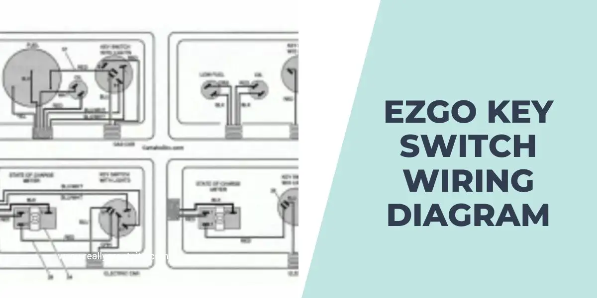
You may also want to refer to my post on EZGO Key Switch Wiring Diagram for details on the wiring connections of the EZGO key switch.
Frequently Asked Questions
Here are some frequently asked questions about the EZGO DCS WIring Diagram:
What are some common issues that can be diagnosed using the EZGO DCS wiring diagram?
The EZGO DCS wiring diagram can help diagnose various electrical issues in a golf cart, including the motor not running, no power to the cart, intermittent power loss, faulty switches or solenoids, and problems with the controller or accelerator pedal.
Can I use the wiring diagram to fix electrical problems myself?
The wiring diagram can be a valuable tool for troubleshooting electrical problems in your EZGO golf cart. It helps you understand the system’s components and their connections, allowing you to identify potential issues.
Can I modify the wiring based on the diagram?
Modifying the wiring of your EZGO golf cart based on the wiring diagram should be done with caution. Any modifications should be performed by a knowledgeable individual or a professional technician to ensure the changes are made correctly and safely.
Conclusion
The EZGO DCS Wiring Diagram is a powerful tool that simplifies the electrical setup of your EZGO golf cart. With its clear and detailed instructions, it empowers users to understand and navigate the complex wiring system effortlessly. By utilizing this modern and user friendly diagram, you can save time and effort when troubleshooting and repairing electrical issues.


