When my Polaris Sportsman 450 ATV started having problems related to the CDI, I was able to use the Polaris CDI Wiring diagram to quickly identify the issue and fix it myself, saving me time and money.
In this blog post, I will share my personal experience with using the Polaris CDI wiring diagram and how it has helped me keep my ATV running smoothly.
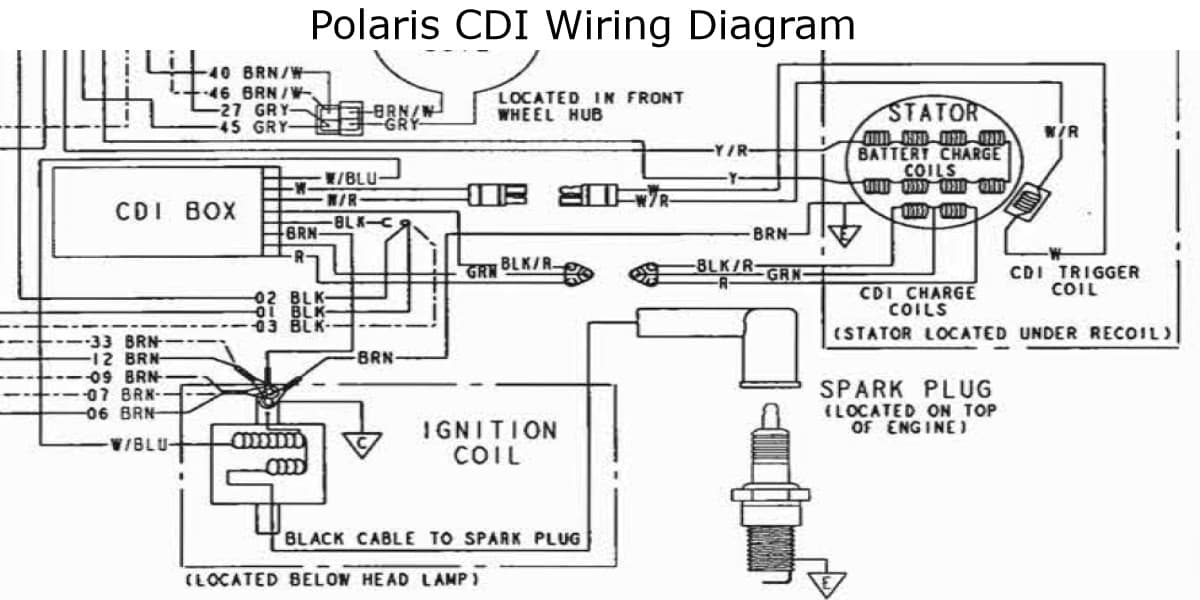
Polaris CDI Wiring Diagram
This Polaris CDI Wiring Diagram shows the layout of the various components of the CDI system, including the ignition coil, stator, and wiring harness:
If you are having starter issues with your Polaris vehicle, check out this Polaris Starter Solenoid Wiring Diagram.
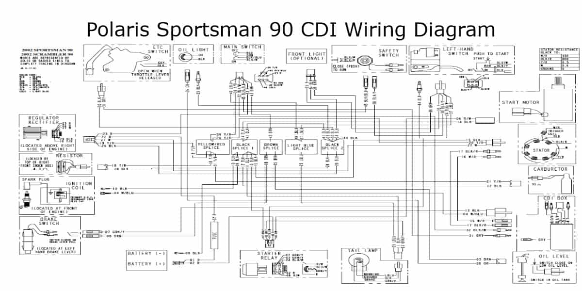
Polaris Sportsman 90 CDI Wiring Diagram
This is the Polaris Sportsman 90 CDI Wiring Diagram:
How to Test CDI Box on Polaris ATV
The steps listed below show how to test the CDI box on your Polaris ATV:
- Take the leads of the multimeter and link them together first.
- A digital multimeter should beep when used, so listen for that.
- Check the continuity of the ground at all of the different sites.
- If your CDI is functioning correctly, there won’t be any noise.
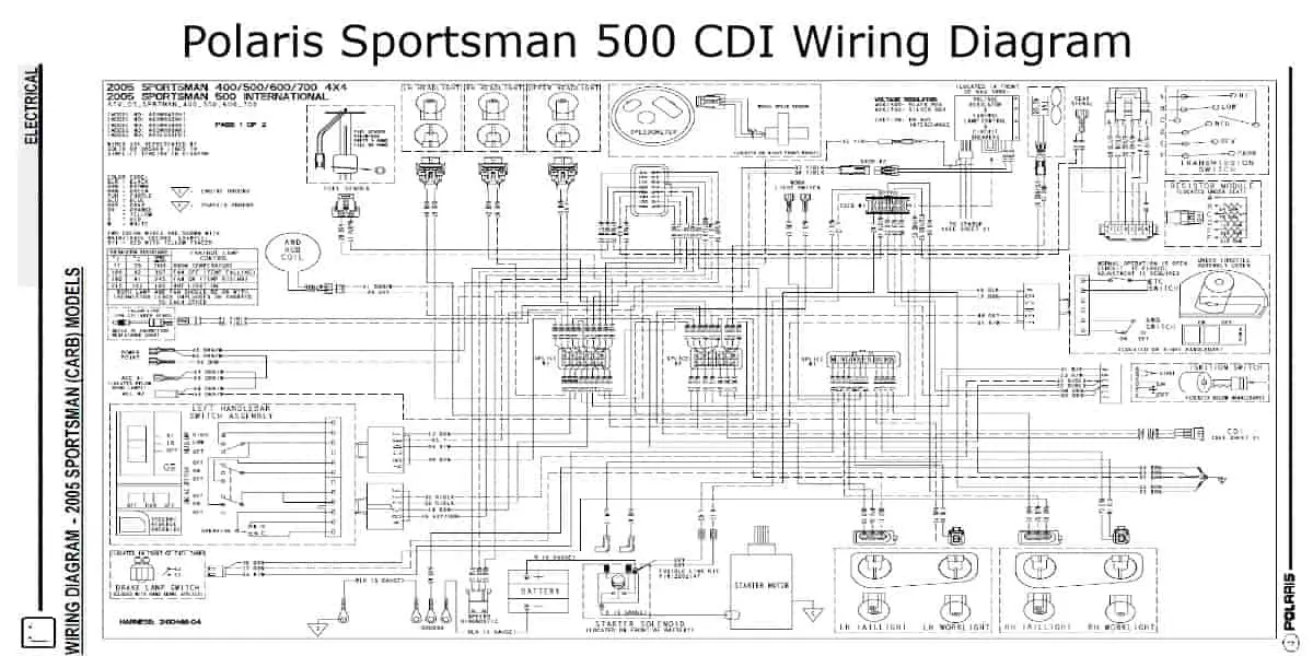
Polaris Sportsman 500 CDI Wiring Diagram
This is the Polaris sportsman 500 CDI wiring diagram:
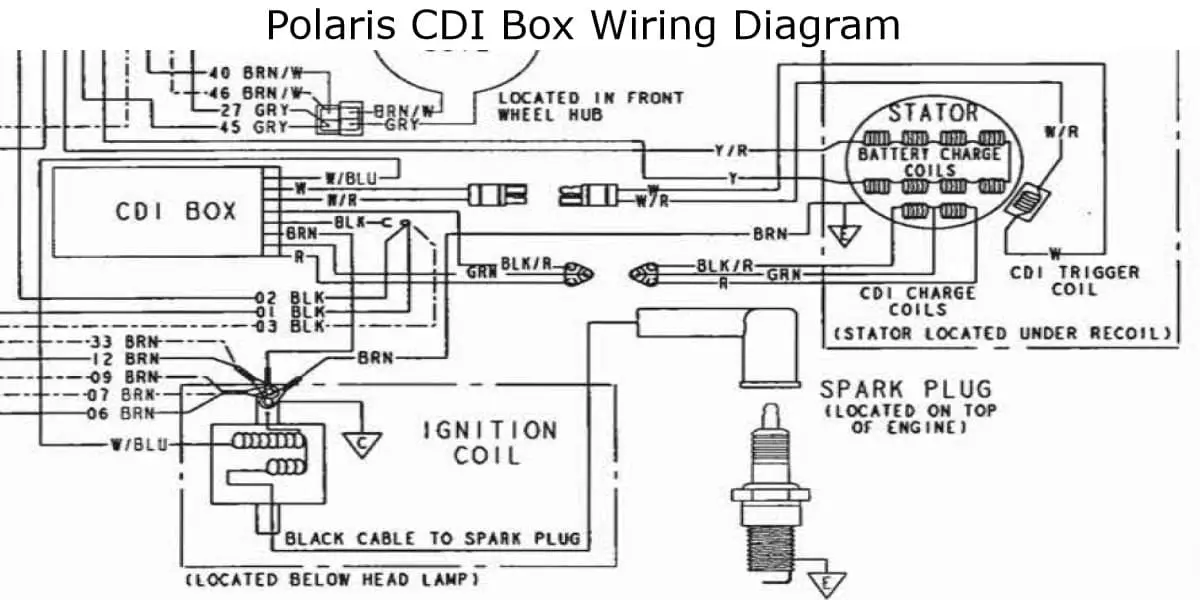
Polaris CDI Box Wiring Diagram
This photo shows the box wiring diagram of the Polaris CDI:
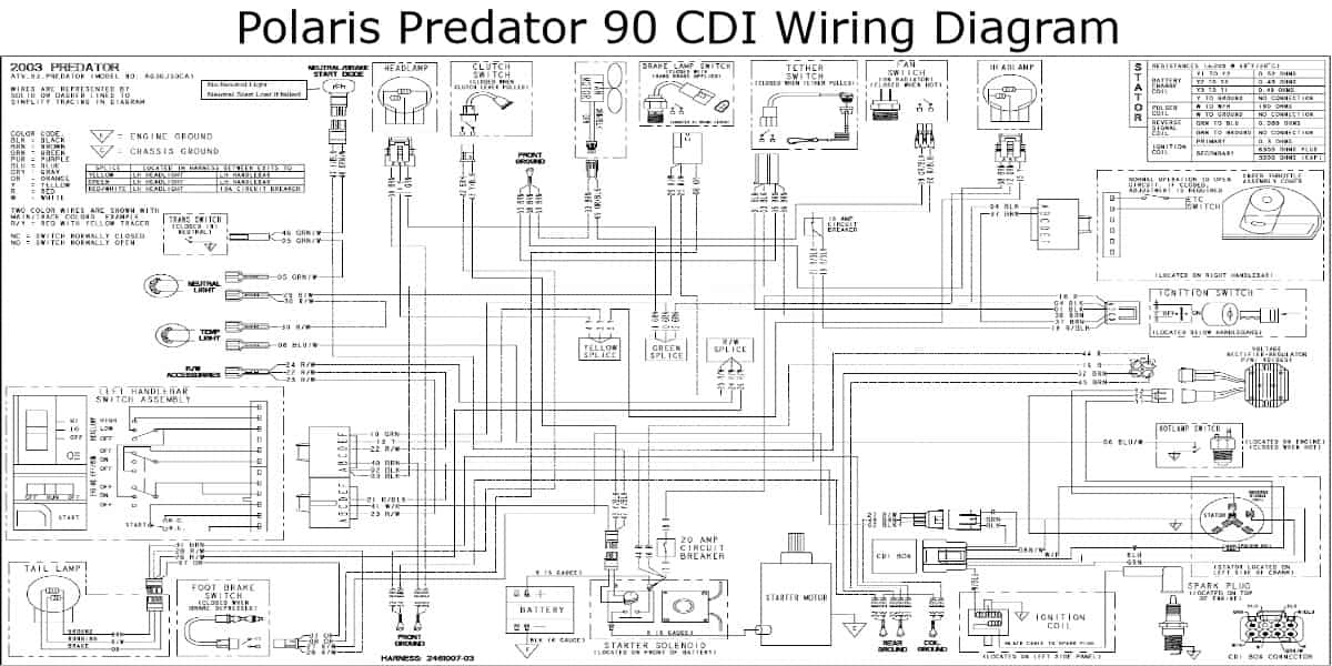
Polaris Predator 90 CDI Wiring Diagram
This is the Polaris Predator 90 CDI Wiring Diagram:
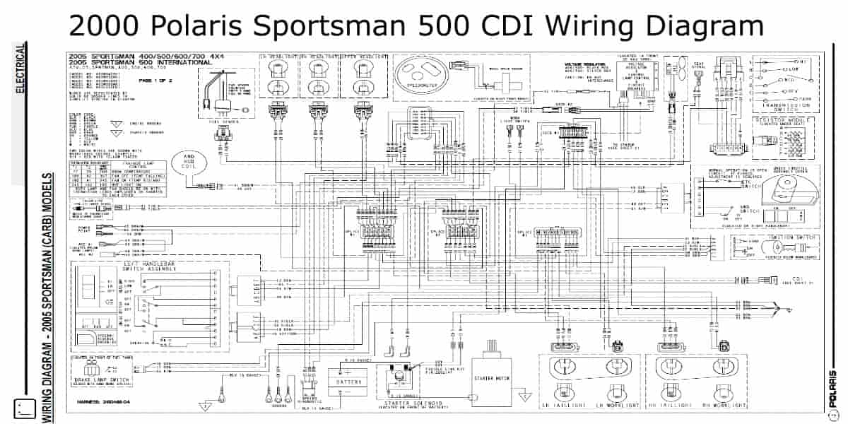
2000 Polaris Sportsman 500 CDI Wiring Diagram
This photo shows the 2000 Polaris Sportsman 500 CDI Wiring Diagram:
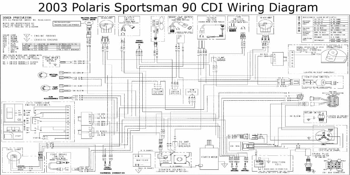
2003 Polaris Sportsman 90 CDI Wiring Diagram
This image shows the 2003 Polaris sportsman 90 CDI wiring diagram:
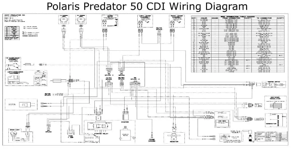
Polaris Predator 50 CDI Wiring Diagram
This is the Polaris Predator 50 CDI Wiring diagram:
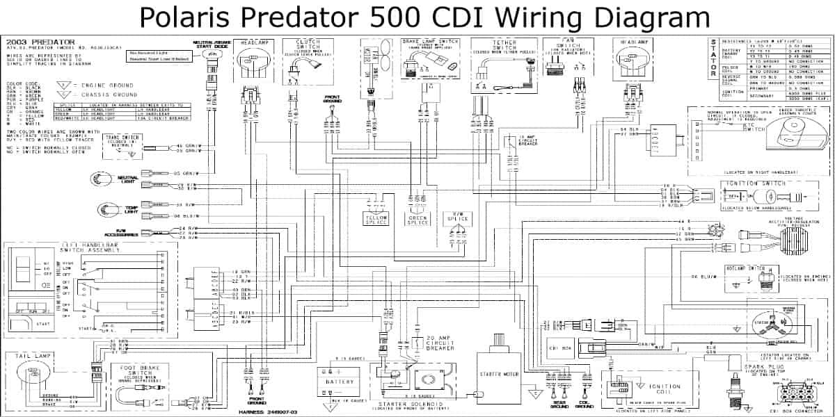
Polaris Predator 500 CDI Wiring Diagram
This is the Polaris Predator 500 CDI Wiring Diagram below:
How to Wire a 4-Pin CDI on A Polaris ATV?
- The 12-volt-n, primarily red, is on the smaller connector. Please attach it to the ignition switch of your ATV.
- The coil-out pin, usually yellow and brown, is located on the upper right side of the larger connector and will be connected to your coil.
- The pickup coil pin is on the larger connector’s upper left side. Connect the stator to the pickup coil pin.
- Ground the motor with the pin on the larger connector’s outer edge.
- The ignition should now work when you turn it on.
Check out this article on the Polaris Ignition Switch Wiring Diagram, as it will help you fix ignition issues with your vehicle.
Conclusion
In this article, I have given several diagrams to aid you in understanding your Polaris’ internal wiring with a detailed Polaris CDI Wiring Diagram, including a step-by-step on how to wire a 4-pin CDI and test the CDI box on your Polaris ATV. Hopefully, this helps you.

