Have you ever had trouble with the wiring for your EZGO tow run switch?
Trust me, I know the feeling.
But, good news: I’ve figured the EZGO Tow Run Switch Wiring Diagram out!
Today, we’re going to look at the wiring diagram and how your EZGO golf cart’s tow switch works.
EZGO Tow Run Switch Wiring Diagram
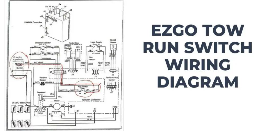
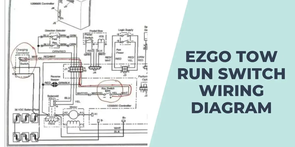
This is the EZGO tow run switch wiring diagram:

Check my post on the EZGO solenoid wiring diagram for an understanding of the EZGO solenoid.
Components of The EZGO Tow Run Switch Wiring Diagram
These are the Components of the EZGO Tow Run Switch Wiring Diagram:
- EZGO Tow Run Switch: This is the main component that controls the operation of the golf cart. It typically has multiple terminals or wires for making connections.
- Battery: The golf cart’s battery is a crucial component that provides power to the vehicle. The wiring diagram will show the battery’s positive (+) and negative (-) terminals and their respective connections.
- Terminal 1: Battery Positive connection – This terminal is responsible for connecting the switch to the positive (+) terminal of the golf cart’s battery, providing the power supply.
- Terminal 2: Battery Negative or Vehicle Frame Ground connection – This terminal connects to the negative (-) terminal of the battery or the vehicle’s frame ground, establishing a grounding point for the electrical system.
- Terminal 3: Controller Input connection – This terminal allows the switch to connect to the input wire of the golf cart’s controller, enabling control over the power flow.
- Terminal 4: Tow/Run Output connection – This terminal connects to the output wire that carries power from the switch to the controller. In the “Tow” mode, it disconnects from the battery positive, effectively cutting off power to the controller. The “Run” mode allows power flow to enable normal operation.
- Controller: The controller is responsible for regulating the power and controlling the operation of the electric motor in the golf cart. The wiring diagram will indicate the connections between the Tow Run switch and the controller.
- Vehicle Frame Ground: The golf cart’s frame serves as the ground for various electrical components. The wiring diagram will illustrate the connection between the battery negative terminal and the vehicle’s frame ground.
- Other Components: Depending on the specific model and features of your EZGO golf cart, the wiring diagram may include additional components such as fuses, relays, key switches, and lights. These components will have their connections shown in the diagram.
For detailed instructions on wiring your EZGO starter generator, check out my comprehensive EZGO starter generator wiring diagram guide.
How to Troubleshoot common issues using the EZGO Tow Run Switch Wiring Diagram
Follow these steps to troubleshoot common issues using the EZGO Tow Run Switch Wiring Diagram:
- Ensure you have access to the accurate and up-to-date EZGO Tow Run switch wiring diagram. The diagram will serve as your reference throughout the troubleshooting process.
- Gather essential tools such as a multimeter, wire connectors, electrical tape, and a screwdriver.
- Identify the specific issue you are experiencing with the EZGO Tow Run switch. Common problems include a complete loss of power, intermittent power loss, or a malfunctioning switch. Understanding the symptoms will guide your troubleshooting efforts.
- Carefully inspect the wiring connections, ensuring they are secure and free from any signs of damage, such as frayed wires or loose terminals. Pay close attention to the connections involving the Tow Run switch, battery, controller, and any additional components. Any visible issues should be addressed by repairing or replacing the affected components or wires.
- Refer to the EZGO Tow Run switch wiring diagram to identify the specific terminals and wires involved in the issue you are troubleshooting. Compare the actual connections to the diagram to ensure accuracy.
- Using a multimeter, check the voltage at different points of the electrical system, such as the battery terminals, the Tow Run switch terminals, and the controller input. Compare the readings to the specifications provided in the wiring diagram. Additionally, test for continuity across wires and connections to ensure there are no breaks or open circuits.
- If the issue persists, follow the circuit path indicated in the wiring diagram. Check for any potential points of failure, such as faulty relays, blown fuses, or loose connections. Test each component along the circuit to identify the specific area where the problem lies.
- Once you have identified the faulty component or connection, take appropriate action to repair or replace it. Ensure all repairs or replacements adhere to the specifications outlined in the wiring diagram.
- After making the necessary repairs or replacements, retest the system using the multimeter to ensure the voltage, continuity, and proper functioning of the EZGO Tow Run switch and related components. Compare the readings to the expected values provided in the wiring diagram.
Benefits of using the EZGO Tow Run Switch Diagram
These are the Benefits of using the EZGO Tow Run Switch Diagram:
- Ensures Correct Connections: With its detailed illustrations and labeled terminals, it helps you identify the specific points of connection for the switch, battery, controller, and other components. By following the diagram accurately, you can avoid any guesswork or potential errors, ensuring that each wire is connected to the appropriate terminal.
- Promotes Safety: The EZGO Tow Run switch wiring diagram plays a crucial role in ensuring a safe wiring process. By adhering to the diagram, you can minimize the risk of electrical hazards, such as short circuits or unintended power surges, thereby protecting both yourself and the golf cart from potential harm.
- Simplifies Troubleshooting: In case of any electrical issues or malfunctions, the EZGO Tow Run switch wiring diagram provides a clear overview of the entire electrical system, allowing you to trace wires, identify potential problem areas, and verify the integrity of the connections.
- Facilitates Upgrades or Modifications: Whether you are adding new accessories, integrating lighting systems, or incorporating advanced features, the diagram serves as a roadmap for integrating these components seamlessly. It helps you understand the existing wiring configuration and guides you in making the necessary modifications without compromising the overall functionality of the Tow Run switch and other essential components.
- Accessible Reference: The EZGO Tow Run switch wiring diagram is a reliable resource for future maintenance, repairs, or upgrades. This accessibility allows you to consult the diagram whenever you encounter wiring related questions or require clarification, even after a significant period of time.
To learn more about the inner workings of your EZGO vehicle, check out our detailed guide on the EZGO 2 Cycle Engine Diagram.
Frequently Asked Questions
Here are some frequently asked questions about the EZGO Tow Run Switch Diagram:
Can I modify the wiring of the EZGO tow run switch?
Modifying the wiring of the EZGO tow run switch is not recommended unless you have advanced knowledge and experience in electrical systems.
Are there any safety precautions to consider when working with the tow run switch wiring?
When dealing with electrical components, it’s important to disconnect the power source, such as the battery, before attempting any wiring work. This minimizes the risk of electrical shocks or damage. Additionally, following proper safety guidelines, such as wearing protective gloves and eyewear, can further ensure your well being.
Why is the wiring diagram important for the EZGO tow run switch?
The wiring diagram helps technicians and DIY enthusiasts understand the electrical connections and troubleshoot any wiring issues that may arise. A clear diagram ensures proper installation and maintenance of the switch, promoting the cart’s reliable and efficient performance.
Conclusion
Understanding the EZGO Tow Run Switch Diagram is crucial for maintaining control and preventing any potential mishaps on the road. By following the guidelines outlined in the diagram, you can easily switch between tow and run modes, ensuring your EZGO vehicle operates seamlessly in any situation.


