
Are you looking to add a light kit to your EZGO golf cart yourself?
But wait! How do you wire it all up correctly?
In this post, I’ll provide the EZGO Light Kit Wiring Diagram to help you understand the electrical connections.
EZGO Light Kit Wiring Diagram
This is the EZGO light kit wiring diagram:

If you are wondering what lights to install, check out my Best EZGO Golf Cart Light Kit picks.
Components of The EZGO Light Kit Wiring Diagram

These are the top 5 components of The EZGO Light Kit Wiring Diagram:
- Headlights: The diagram will show the wiring connections for the headlights, including the positive (+) wire and the negative (-) wire. The positive wire is usually connected to a power source, such as the positive terminal of the golf cart’s battery. The negative wire is typically connected to a suitable ground, such as the golf cart’s frame.
- Taillights: The diagram indicates the positive and negative wires for the taillights. The positive wire is connected to a power source, such as the battery’s positive terminal, and the negative wire is connected to a suitable ground.
- Turn Signals: The wiring diagram illustrates the connections for the turn signal system, which may include a flasher unit, turn signal switch, and indicator lights. It shows the wiring for the flasher unit, the turn signal switch, and the left and right turn signal wires. The flasher unit is connected to a power source, and the turn signal switch connects to the indicator lights and the respective left and right turn signal wires.
- Brake Lights: The diagram displays the wiring connections for the brake lights. It shows the positive wire and the negative wire. The positive wire is connected to a power source, such as the positive terminal of the battery, and the negative wire is connected to a suitable ground.
- Horn: The wiring diagram will include the connections for the horn. It will show the positive wire and the negative wire for the horn. The positive wire is connected to a power source, such as the battery’s positive terminal. The negative wire is connected to a suitable ground.
For a detailed guide on EZGO starter generator wiring, you can refer to EZGO starter generator wiring diagram.
How to Install Light Kits on EZGO Golf Cart
Follow these steps to install light kits on EZGO Golf Cart:
- Preparation:
- Disconnect the battery to ensure safety.
- Gather all the tools and components you’ll need for the installation.
- Front Headlights Installation:
- Remove the front body cowl of the golf cart (if recommended by your kit’s instructions) to ease the installation of headlights.
- Use the headlight template provided in the kit to mark the cutting area on the front cowl for each headlight.
- Carefully cut out the marked areas using a Dremel tool or a jig saw.
- Smooth the edges with a file or sandpaper.
- Install the headlights in the cutouts and secure them, but don’t fully tighten until the wiring is complete.
- Rear Taillights Installation:
- Position the taillight templates on the rear body of the cart, following the specific measurements provided in your kit.
- Mark and cut out the areas for each taillight.
- Smooth out the cut edges and install the taillights, similarly leaving final tightening until after wiring.
- Wiring:
- Run the wiring harness from the front to the back of the golf cart, following the frame to avoid areas that could pinch or damage the wires.
- Connect the headlights and taillights to the wiring harness, paying attention to positive and negative connections.
- Secure the wiring harness to the frame with wire ties, adjusting for a snug fit without fully tightening until you confirm the lights work.
- Power Connection:
- Connect the wiring harness to your golf cart’s power supply, following the kit’s instructions for whether to connect to the battery or another power source.
- Ensure all connections are secure and insulated to prevent shorts.
- Switch Installation:
- Install the light switch in a convenient location on the dashboard.
- Drill a hole for the switch if necessary, then connect it to the wiring harness.
- Securely fasten the switch and ensure it operates smoothly.
- Final Checks and Adjustments:
- Reconnect the golf cart’s battery and turn on the lights using the installed switch to test.
- Check both the front headlights and rear taillights to ensure they are working correctly.
- Make any necessary adjustments to the light direction for optimal visibility.
- Once satisfied, fully tighten all lights into position and ensure all wire ties are securely fastened.
- Cleanup:
- Reinstall any parts of the golf cart body that were removed.
- Double-check your work area to ensure no tools or spare parts are left inside or around the golf cart.
- Test Drive:
- Take your golf cart for a test drive in a safe area to ensure everything is working as expected, especially in low light conditions to test the effectiveness of your new lights.
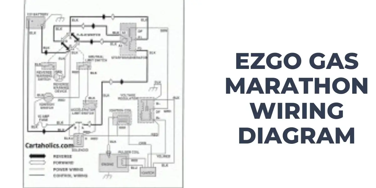
For more information on wiring diagrams specific to more EZGO models, refer to my EZGO Marathon Wiring Diagram guide.
Troubleshooting Common Issues Using the EZGO Light Kit Wiring Diagram
Follow these steps to troubleshoot common issues using the EZGO Light Kit Wiring Diagram:
- Lights not working at all:
- Check the power source: Ensure that the power source, such as the battery, is fully charged and provides voltage to the light kit.
- Verify connections: Review the wiring connections according to the diagram. Double-check that all wires are securely connected to the appropriate terminals and that there are no loose or damaged connections.
- Test the bulbs: Check if the bulbs are functioning properly. Replace any burned-out bulbs as needed.
- Lights dim or flickering:
- Inspect the power supply: Verify that the power source is providing a steady voltage without fluctuations. If necessary, charge or replace the battery.
- Check for loose connections: Ensure that all wiring connections are tight and secure. Loose connections can result in insufficient power flow and cause dim or flickering lights.
- Examine the ground connections: Ensure the negative (-) wires are properly grounded. Clean any corrosion or debris from the grounding points and ensure a solid connection.
- Lights not functioning correctly (e.g., wrong light flashing, lights staying on):
- Review the wiring connections: Refer to the wiring diagram to confirm that all connections are correctly made. Ensure each wire is connected to the appropriate switch, relay, or indicator light, as indicated in the diagram.
- Inspect switches and relays: Check the switches and relays associated with the malfunctioning lights. Ensure they are in good condition and functioning correctly. Replace any faulty switches or relays.
- Blown fuses or circuit breaker tripping:
- Check the load on the circuit: Make sure that the total electrical load of the light kit is within the capacity of the circuit. Overloading the circuit can cause fuses to blow or breakers to trip. Consider redistributing the load or upgrading the circuit if necessary.
- Inspect for short circuits: Look for any exposed or damaged wires that may be causing a short circuit. Repair or replace any damaged wiring and secure it properly to avoid contact with metal surfaces.
For detailed instructions on wiring the EZGO ignition switch, refer to our comprehensive guide on the EZGO Ignition Switch Wiring Diagram.
FAQs on the EZGO Light Kit Wiring Diagram
These are the most frequently asked questions about the EZGO Light Kit Wiring Diagram:
What do the different colors of wires in the diagram represent?
Common color codes include red or black for positive (+) wires and white or gray for negative (-) or ground wires.
Can I use a universal wiring diagram for my EZGO light kit?
Using the wiring diagram specific to your EZGO light kit model and year is best. While there may be similarities between different light kits, there can also be variations in wiring configurations, wire colors, and specific connections. Using the correct diagram ensures accurate wiring and reduces the risk of errors.
Conclusion
Whether you’re an experienced DIY enthusiast or a beginner, this EZGO Light Kit Wiring Diagram will provide you with the knowledge and confidence to tackle your EZGO Light Wiring project. So, enjoy your newly illuminated ride and have a fantastic time cruising with style!

