
Today, we’re diving into the world of differentials with an EZGO differential diagram that’ll have you feeling like a mechanical genius in no time.
Whether you’re a seasoned pro or a curious newbie, understanding how the differential operates is crucial for a smooth ride on the green.
So grab your wrench and get ready to unlock the mysteries of this vital component.
EZGO Differential Diagram
This is the EZGO differential diagram:

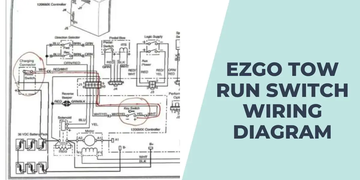
If you’re interested in a deep understanding of the EZGO tow run switch, check my post on the EZGO tow run switch wiring diagram.
Understanding the Ezgo Differential
The EZGO differential diagram refers to a diagram that illustrates the components and operation of the differential system in an EZGO vehicle. The differential is an essential part of the drivetrain, responsible for allowing the wheels on the same axle to rotate at different speeds while transmitting power from the engine to the wheels. This capability is crucial for smooth turning and maneuverability.
Components of The EZGO Differential Diagram
Here are the components of the EZGO Differential Diagram:
- Ring gear: It is a large gear attached to the differential carrier. The ring gear receives torque from the engine or transmission and transfers it to the differential assembly.
- Pinion gear: The pinion gear is a smaller gear connected to the driveshaft. It meshes with the ring gear and transmits rotational force to the differential assembly.
- Differential carrier: The carrier houses the differential assembly and provides support for the gears. It is mounted within the axle housing and rotates along with the wheels.
- Differential assembly: This assembly consists of a set of gears, including side gears and spider gears. The side gears are connected to the axle shafts, while the spider gears are located in the center. The differential assembly allows the wheels on the same axle to rotate at different speeds while distributing torque.
- Axle shafts: These are shafts that connect the differential assembly to the wheels. The axle shafts transmit power from the differential to the wheels, enabling them to rotate.
- Bearings: Bearings support the rotating components of the differential, allowing smooth movement and reducing friction.
If you’re interested in optimizing the performance and lifespan of your golf cart battery, check out our guide on the Golf Cart Battery Watering System.
How to Troubleshoot Common Issues Using the EZGO Differential Diagram
Follow these steps to Troubleshoot Common Issues Using the EZGO Differential Diagram:
- Noise or Grinding Sounds:
- Check for any loose or damaged components in the differential assembly, such as worn gears, damaged bearings, or loose fasteners. Refer to the diagram to identify the specific parts.
- Inspect the ring gear and pinion gear for any signs of wear or damage.
- Ensure that the differential carrier is properly aligned and securely mounted in the axle housing.
- Excessive Vibration:
- Inspect the differential assembly for any imbalances or misalignments. Refer to the diagram to verify the correct positioning of the gears and other components.
- Check the axle shafts for any bends or damage that could cause vibration.
- Ensure that the bearings supporting the differential assembly are in good condition and properly lubricated.
- Uneven Tire Wear:
- Verify that the differential is functioning correctly and distributing power evenly to both wheels. Refer to the diagram to understand the operation of the differential assembly.
- Check the axle shafts and wheel bearings for any signs of wear or damage that could cause uneven tire wear.
- Inspect the tires themselves for any abnormalities, such as improper inflation, alignment issues, or worn tread patterns.
- Difficulty Turning or Maneuvering:
- Confirm that the differential is allowing the wheels on the same axle to rotate at different speeds during turns. Refer to the diagram to understand the differential’s operation during cornering.
- Check the steering components, such as tie rods and steering linkage, for any wear or damage that could affect maneuverability.
- Ensure that the differential carrier and axle housing are in good condition, with no obstructions or restrictions on movement.
- Leaks or Fluid Loss:
- Inspect the differential assembly for any signs of leaks, such as fluid stains or drips. Refer to the diagram to identify the locations of seals and gaskets.
- Check the fluid level in the differential and top up if necessary using the recommended lubricant.
- Identify any damaged seals or gaskets and replace them accordingly.
Frequently Asked Questions
Here are the frequently asked questions about the EZGO Differential Diagram:
What is the purpose of the EZGO differential diagram?
The EZGO differential diagram serves as a visual representation of the differential system in an EZGO vehicle. It helps individuals understand the components and their interactions, aiding in maintenance, troubleshooting, and identifying potential issues.
Can I use the EZGO differential diagram to repair or replace components myself?
While the diagram provides valuable information about the differential system, it is essential to have proper mechanical knowledge and experience to perform repairs or replacements. It is generally recommended to consult a qualified technician or EZGO dealership for complex repairs or replacements.
Are the components in the differential diagram interchangeable between different EZGO models?
The components in the differential diagram may vary between different EZGO models and model years. It is crucial to ensure you are referencing the correct diagram specific to your vehicle’s make, model, and year to accurately identify and understand the components.
Conclusion
Exploring the EZGO differential diagram has been an enlightening journey. We’ve delved into the intricate mechanisms that make this component crucial for a smooth ride in golf carts and utility vehicles. By understanding its inner workings, we can appreciate how power is distributed and the role it plays in maneuverability and stability.
Whether you’re an enthusiast, a technician, or simply curious, this diagram has offered valuable insights into the fascinating world of automotive engineering. Remember, knowledge empowers us to make informed decisions and fosters a deeper appreciation for the engineering marvels that surround us. Keep exploring and embracing the wonders of technology!


